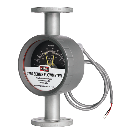
7750 with Inductive Slot Sensor
Inductive Slot Sensor
Inductive Slot Sensor alarm available for 7710, 7720, 7750 Series
All 7710, 7720 and 7750 Series flowmeters may be fitted with one inductive slot sensor.
Inductive sensors are 2-wire, DC low current devices and are designed to be used with a remote barrier/switch isolator capable of powering the sensor and providing the desired switching option(s). Barrier/switch isolators are available with 220 VAC, 110 VAC or 24 VDC supply voltage requirements, contain single pole, double throw (SPDT) relays, and are DIN rail mountable. (Only 24 VDC units are actually powered by the rail.) See barrier/switch isolator specifications for electrical connections and further details.
The operating temperature range for this sensor is -13° F to158° F (-25° C to 70° C).
Note: We can supply the isolator / barrier upon request, but the user must provide the power supply voltage.
ELECTRICAL SPECIFICATIONS
Type | Inductive |
Supply Voltage | 5-25V DC (Switch Isolator) |
Output | NAMUR |
Output Load Current | <=1 mA – Float Present >= 3 mA (15 mA Max.) –Float Absent |
Switching Frequency | 5 kHZ |
Housing Rating | IP67 |
Wiring | 2 Conductor, NAMUR, Pos = Brown, Neg.= Blue |
Terminals | #1=Pos., #2=Neg. |
Pepperl & Fuchs Slot Sensor Approvals: | UL: General Purpose FM: Intrinsically Safe CSA: Intrinsically Safe CENELEC: Intrinsically Safe |